PLC Unit Test — Automated Testing & System Validation Framework
.png)
I started this project because I kept seeing the same problem in controls work: after a PLC logic change, there is always a need to verify not only the new behavior, but also the old behavior that was already working.
Sometimes the change is small: an alarm limit, a function block adjustment, a sequence update, a permissive condition, or a tag mapping correction. But even a small change can affect other parts of the logic, especially when the system has shared tags, reused function blocks, interlocks, or dependencies between devices.
That is where manual testing becomes repetitive. You force a value, wait, check the alarm, check the HMI, reset the value, change another condition, and repeat the same process again after the next update.
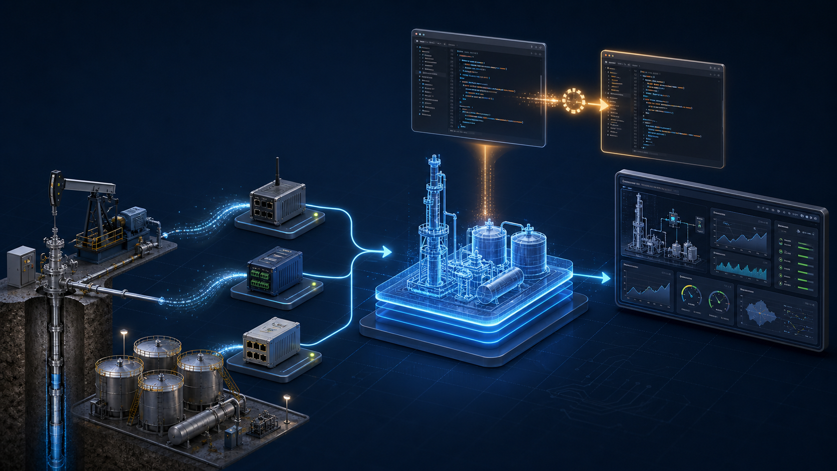
Architecture: How Validation Flows Through the System
The architecture is organized in three layers, and validation flows through them in four operations:
1- Data Injection. At the control layer, the platform connects directly to the PLCs to write simulated process values, setpoints, and command bits.
2- Logic Validation. Still at the control layer, it reads back alarms, status bits, and calculated values to confirm the logic reacted correctly.
3- Mapping and Data Consistency. At the supervisory layer, the platform verifies the SCADA against the controller, confirming that what the PLC produces is what the operator actually sees.
4- Reporting. Every step of the chain is documented for review and reuse.
Because the platform is built on protocol-agnostic drivers, any driver can play any role in a test. This enables a validation scenario that is usually overlooked: cross-protocol consistency checking. Modern controllers often expose the same data through multiple open ports at once — S7, Modbus TCP, OPC UA — and every path is expected to report the same value. The platform can read the same data point through each available protocol and confirm they all match, catching mapping, scaling, or configuration errors that would otherwise only appear later as "the HMI shows one thing and the historian shows another." This is, in fact, the scenario I am currently using to test the platform itself. The protocols shown in the diagram (S7 Plus, OPC UA) are one example configuration, not a fixed architecture.
This project is my attempt to bring a more repeatable validation workflow into PLC development. It is not meant to replace SAT. SAT is the final site acceptance test with the client, real instruments, real devices, real field conditions, and formal sign-off. This platform is focused on internal engineering validation, regression testing, and simulated or partially simulated scenarios before that stage.
The idea is to create tests for PLC logic the same way software teams create repeatable tests for code: define the input conditions, execute the logic, read the result, and compare it with the expected behavior.
In this case, the “inputs” are PLC tag values, simulated process values, permissive states, or command bits. The “outputs” are alarms, status bits, calculated values, HMI/SCADA-facing tags, or any other value that proves the logic reacted correctly.
Test Editor
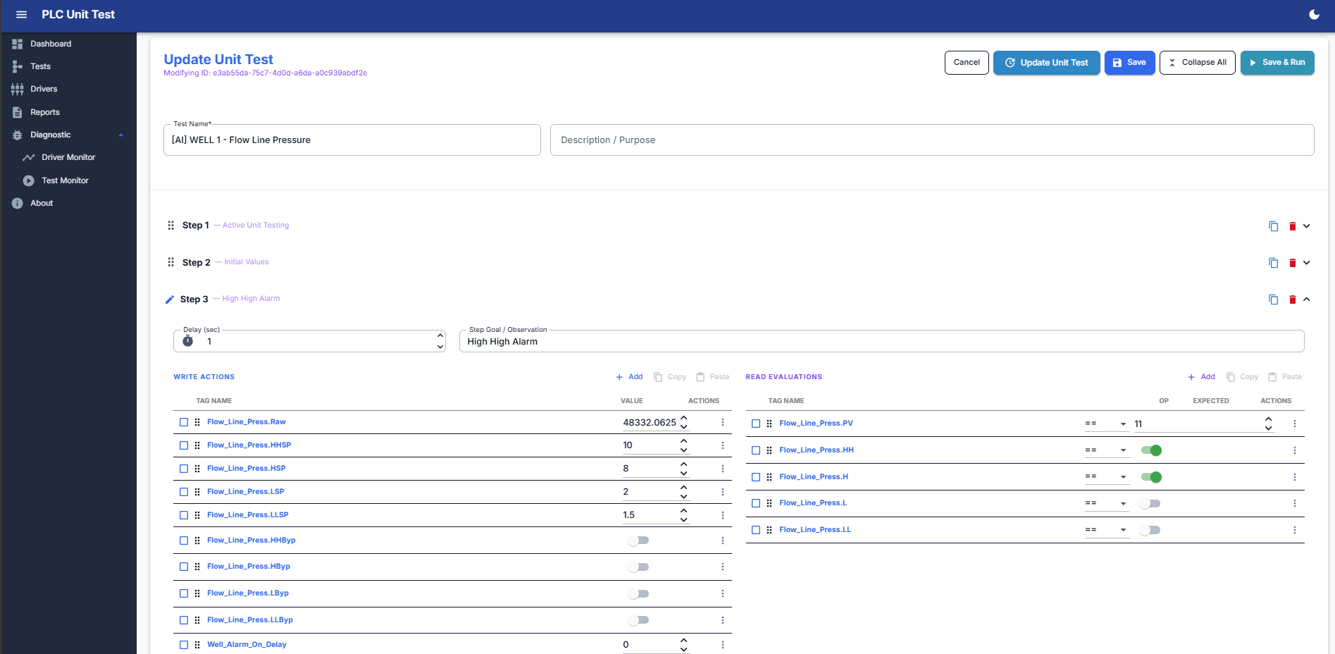 Internally, each test is built as a sequence of steps. A step can write one or more values to PLC tags, wait a configured delay, read live values back from the controller, and evaluate those values against expected conditions. The evaluation supports equal, not equal, greater than, less than, between, out of range, and bit-level checks.
That makes it useful for testing function blocks, analog scaling, alarm behavior, motor sequences, valve logic, permissives, interlocks, and other control logic that normally requires repeated manual forcing and checking.
One of the biggest use cases is regression testing. If I update old PLC logic, I can re-run the same saved tests and confirm that the previous behavior is still correct. That is the part I care about most: catching problems earlier, before they become expensive during formal testing or commissioning.
Execution Monitor
 The Execution Monitor provides a live view of each test sequence after it has been created. This screen allows the engineer to review the configured steps, execute the test, re-run it when needed, and save the result as a validation report.
Each step in a sequence has two sides: the write operations that inject the test conditions into the PLC, and the live evaluations that read values back and compare them against the expected result — each with its own comparison rule. In this example, step S1 sets the initial values of an analog block (engineering units and the four alarm setpoints) and immediately verifies that the controller accepted every value.
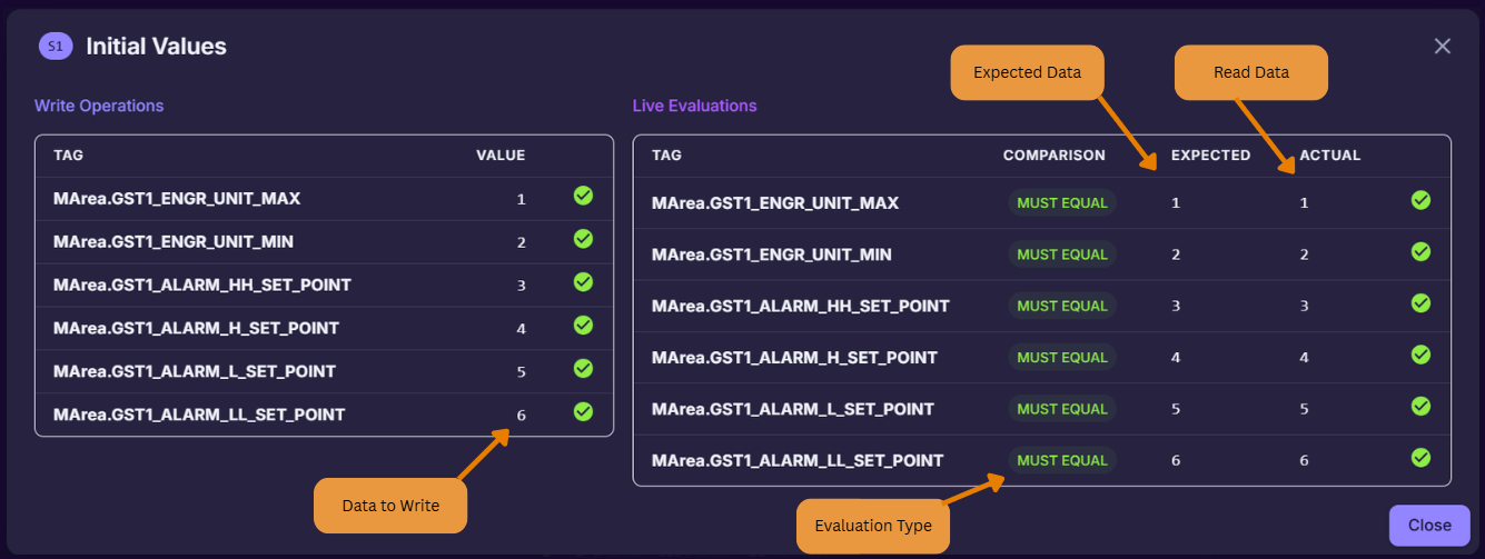 This view is important because it connects the test definition with the real validation result. It is not only showing PLC data; it is confirming whether the PLC logic reacted correctly to the injected conditions.
The monitor supports step-by-step review, full test execution, re-running previous tests, and saving completed results for reporting. This makes it useful for regression testing, internal validation, and simulated scenario testing before formal project execution.
In this example, the platform is validating an analog pressure block by writing simulated values into PLC tags and checking that the expected process value and alarm states match the live controller response.
Driver/tag explorer
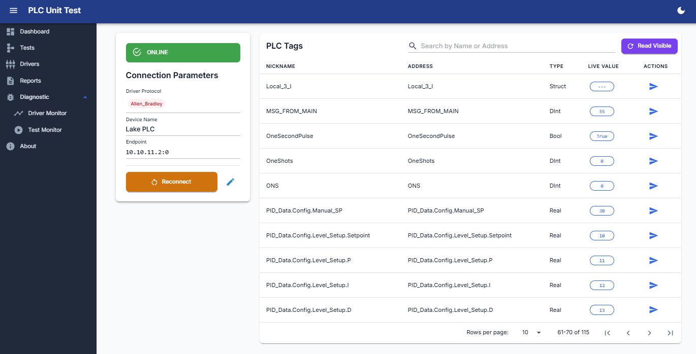 The other challenge was communication. I did not want the test engine to depend on only one PLC brand or one protocol, so I built the system around protocol-specific drivers and a common live tag layer.
The application supports or was designed around Siemens S7, Allen-Bradley / EtherNet/IP, Modbus TCP, OPC UA, and MQTT / Sparkplug B. When the protocol supports browsing, the platform can explore and import tags directly. When it does not, like with Modbus, tags can be manually mapped or imported.
From the software side, the project is a layered .NET application using C#, Blazor Server, MudBlazor, LiteDB, PLC runtime services, live tag management, a test execution engine, and PDF/Excel reporting. The important part was not just using those technologies individually, but connecting them into one workflow: configure drivers, import tags, build tests, execute steps, evaluate results, and save reports.
Dashboard
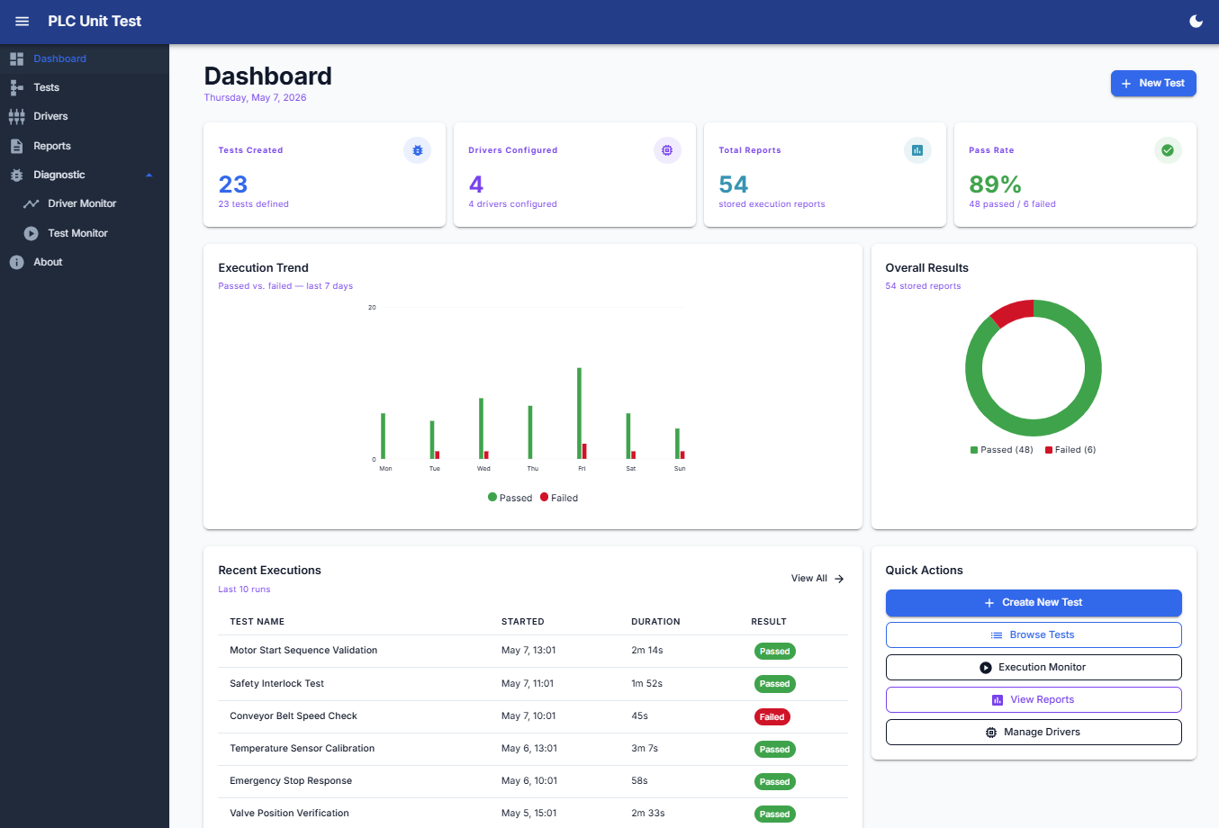 There were also control-system-specific problems to consider. Running automated tests against PLC tags is not the same as running normal software unit tests. If two tests write to the same memory area or device at the same time, they can interfere with each other. That means parallel execution needs rules around tag collisions, shared resources, and safe test boundaries.
This is why I see this project less as a “dashboard” and more as a validation framework. It connects controls engineering, industrial communication, software development, and reporting into one practical tool.
PDF/Excel report
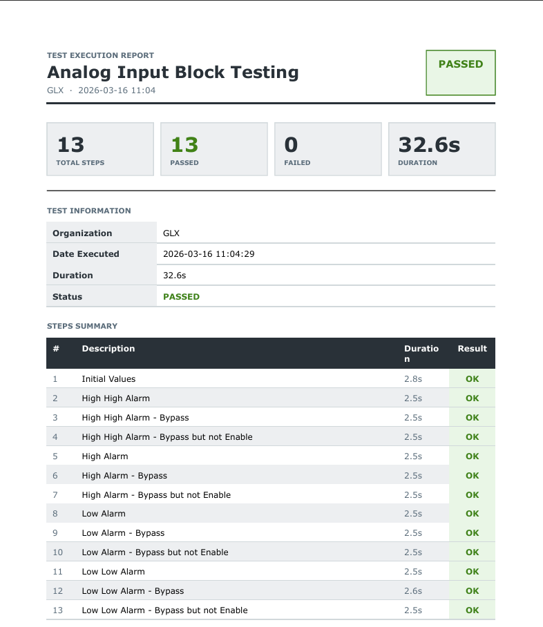 The last part of the workflow is reporting. After a test is executed, the platform stores the result and can generate a PDF or Excel report with the execution status, duration, total steps, passed/failed count, and a step-by-step summary.
This is important because validation is not only about seeing a green result on the screen. The result also needs to be documented, reviewed, and reused later when the logic changes again.
For example, in one analog input block test, the report captured 13 validation steps covering initial values, high-high alarm behavior, high alarm behavior, low alarm behavior, low-low alarm behavior, and bypass conditions. That type of report makes it easier to prove what was tested and what the result was.
The PDF report gives a clean summary, but the Excel export provides the detailed engineering evidence. It shows each test step with the values written into the PLC, the tags read back from the controller, the expected conditions, and the actual results.
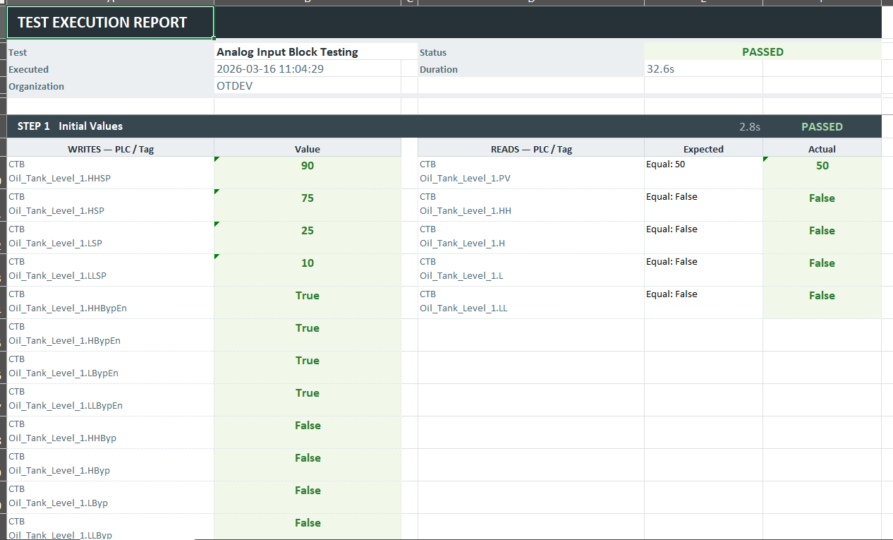 This is useful when the team needs to review exactly what was injected, what was evaluated, and why a step passed or failed. For me, this is important because validation should not only produce a pass/fail result. It should also preserve enough detail to understand and repeat the test later.
The main value is simple: reduce repetitive manual testing, make PLC logic validation more repeatable, and give the engineering team a faster way to verify behavior after changes.
This is not a lab exercise, the framework currently supports validation work on real control systems in the water treatment and oil & gas sectors in the United States, where documented, repeatable testing directly reduces commissioning time and the risk of undetected logic regressions in critical infrastructure.
Oscar Calix
Control System Engineer
Cloud computing for OT, industrial data pipelines, SCADA supervision, and full-stack tools for automation workflows.