RETURN_TO_REGISTRY
Pure PLC Hierarchical Recipe Engine & Dynamic Step Execution
SiemensS7-1200TIA PortalSCLUDTState MachineHMIKT400VFDDataLogWeb ServerPROFINETModbusAutomationArchitecturePLCEdge
Executive Overview
Role: Lead Automation Engineer / Control Systems Architect
Platform: Siemens SIMATIC S7-1200 PLC, Siemens SIMATIC HMI Basic Panel (KP400), Yaskawa V1000 VFD
Scope: Control system design, software architecture standardization, and field commissioning across 11 of 12 industrial textile processing machines
Stack/Technologies: Siemens TIA Portal, Structured Control Language (SCL), Ladder Logic (LAD), Embedded S7 Web Server, DataLog API
1. Context & Objectives
The project required automating a fleet of industrial batch dyeing and chemical treatment machines. Each unit processes raw textile garments requiring specific multi-phase chemical dosing, thermal ramping, and mechanical agitation sequences based on material composition and load weight.
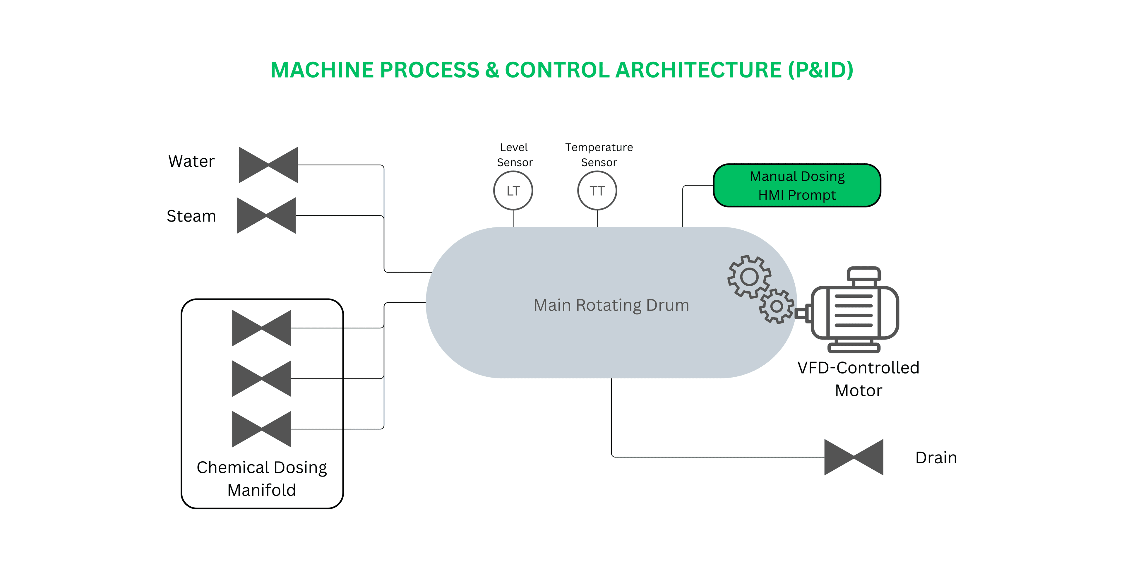
Actuation & Sensor Footprint
Thermal Control: Direct steam injection valves and inline temperature feedback loops.
Fluid Management: Water inlet valves, drain solenoids, maximum-level regulation sensors, and chemical dosing manifolds.
Mechanical Drive: Variable Frequency Drive (VFD) controlling a heavy rotating drum (speed setpoints, direction, cycle duty time).
Primary Objective
Deliver a fully dynamic, configurable multi-step batch execution engine running directly on edge hardware without relying on a centralized SCADA server or PC-based runtime.
2. Technical Limitations & Challenges
Hardware Constraints: The control hardware was restricted to an entry-level Siemens S7-1200 PLC and a basic Siemens KP400 HMI. The platform lacked native advanced recipe management features found in higher-tier HMI/SCADA runtimes.
Machine-to-Machine Physical Variances: The 11 target machines were not physically identical. Units varied in physical size, dosing manifold configurations (varying numbers of available chemical dosing valves), and water level sensing instrumentation, requiring a control architecture that could adapt dynamically to per-machine hardware topologies.
Concurrent Access Risk: Standard array reads during runtime present a major operational risk: if an operator modifies a recipe on the HMI while a machine is actively running that recipe, the execution state can become corrupted mid-cycle.
Traceability Without a Database: The plant had no active database server connection, yet required audit trails and batch telemetry for quality control.
3. Engineering Solution & Architecture
A. Hierarchical UDT Data Model
The system was engineered around a nested array of User-Defined Data Types (UDTs) stored inside retentive Data Blocks (DBs):
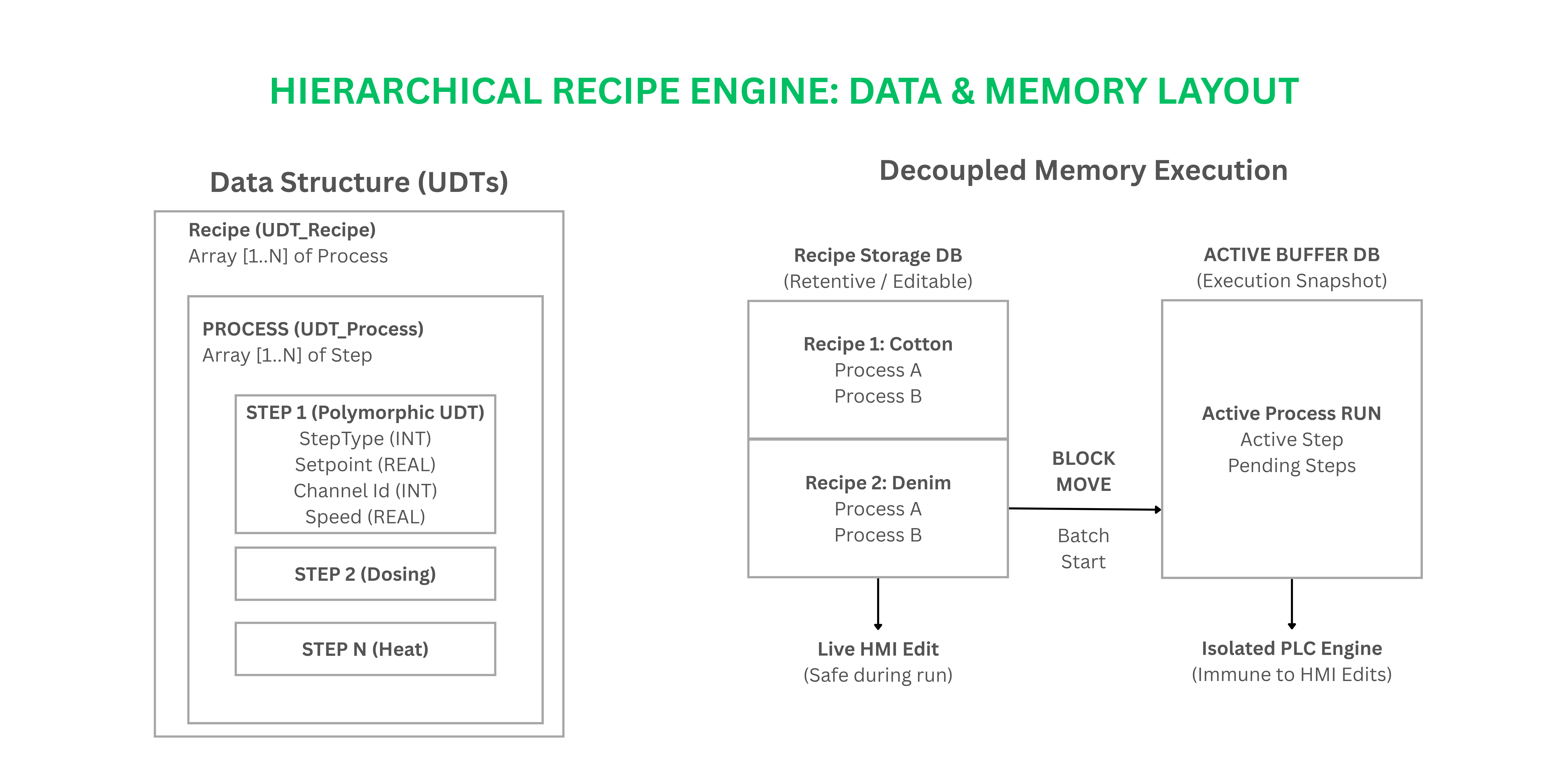 Each Step UDT encapsulates atomic parameters: step type identifier, target temperature setpoint, drum VFD speed/direction, chemical manifold valve index, step timer, and water fill thresholds.
B. Memory Decoupling (Active Snapshot Buffer)
To solve the concurrent access problem, the execution memory was decoupled from the recipe storage memory:
Batch Load: When a batch is initiated, the selected
Recipe UDTstructure is cloned via block memory transfer (BLKMOV) into a dedicated Active Process Snapshot Buffer (a runtime DB).Execution: The PLC step engine processes transitions exclusively from this Snapshot Buffer.
Live Edits: Plant managers can edit, create, or overwrite recipes in the main storage DB via the HMI while the machine is actively executing a batch without affecting the running cycle.
C. Polymorphic Step Execution Logic
During sequence evaluation, the PLC step engine branches execution dynamically based on an enumerated StepType field inside the active Step UDT:
Thermal Ramp / Hold: Actuates steam control valves until reaching setpoint and manages hold timers.
Drum Agitation: Sets VFD speed references (Hz), target rotation direction (CW/CCW), and run/rest duty cycles.
Chemical Dosing (Hardware-Abstracted Dual-Branch):
Automatic Mode: Evaluates target valve indices against the machine's local configuration mapping. The engine actuates specific solenoid manifold outputs to meter bulk liquid additions while enforcing bound checking against that specific machine's max valve count.
Manual Mode: Pauses process progression, triggers audible/visual HMI alarms, and displays specific ingredient loading parameters. The cycle resumes only upon explicit operator confirmation at the HMI.
Level Control: Regulates water fill/drain cycles using digital high-level thresholds and analog feedback.
D. On-Board Traceability (Zero-SCADA Logging)
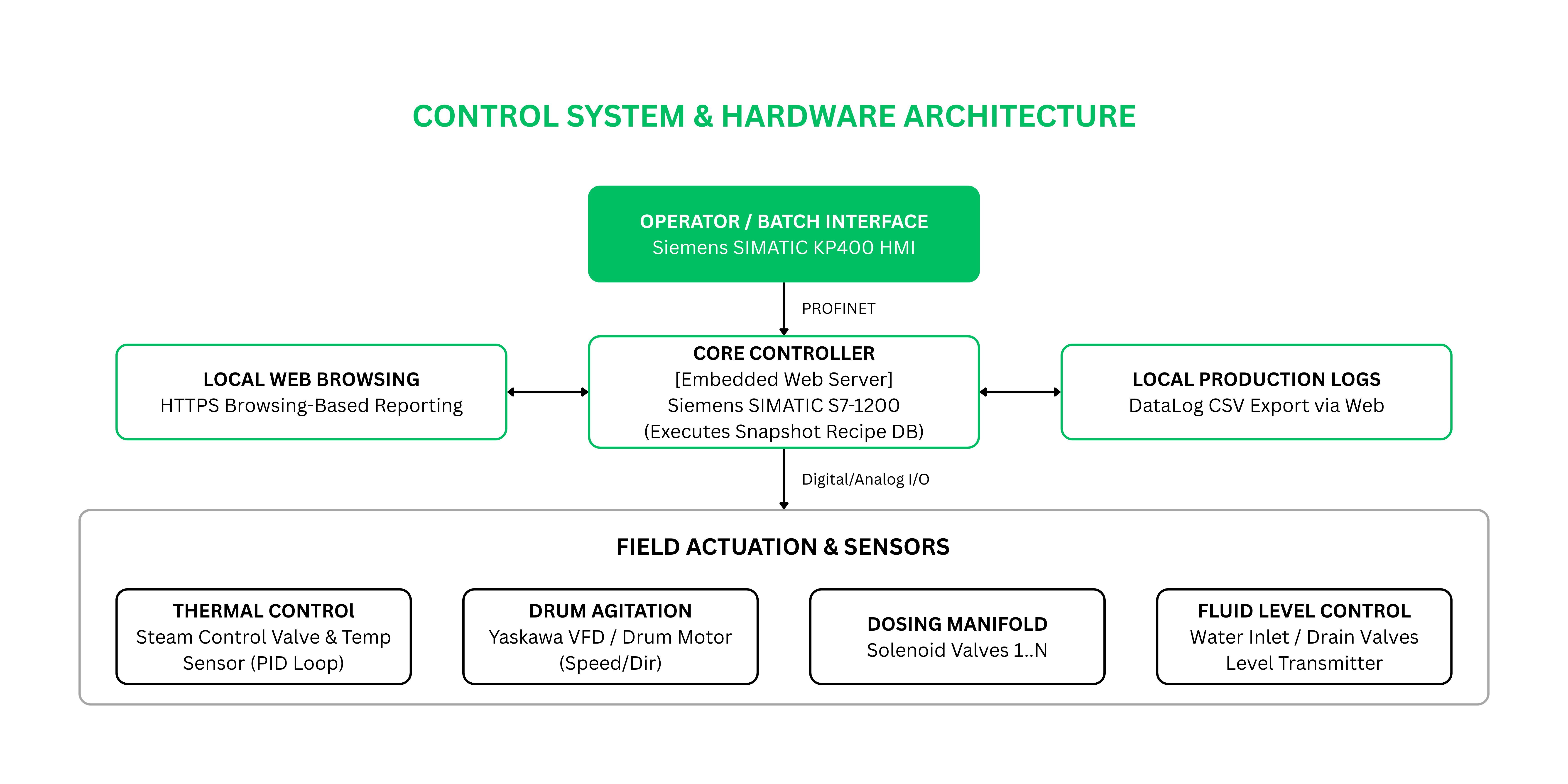
To achieve batch logging on an S7-1200 without external database middleware:
Integrated Siemens
DataLogCreate,DataLogWrite, andDataLogOpensystem blocks directly into the execution state machine.Logged time-stamped batch metrics (Batch ID, Recipe ID, target vs. actual temperatures, step elapsed times, and manual intervention logs) to non-volatile memory upon step transitions.
Configured the embedded Siemens S7-1200 Web Server to expose generated
.CSVlog files via HTTPS, allowing plant engineers to download production reports directly through a standard web browser.
4. Field Deployment & Standardization Strategy
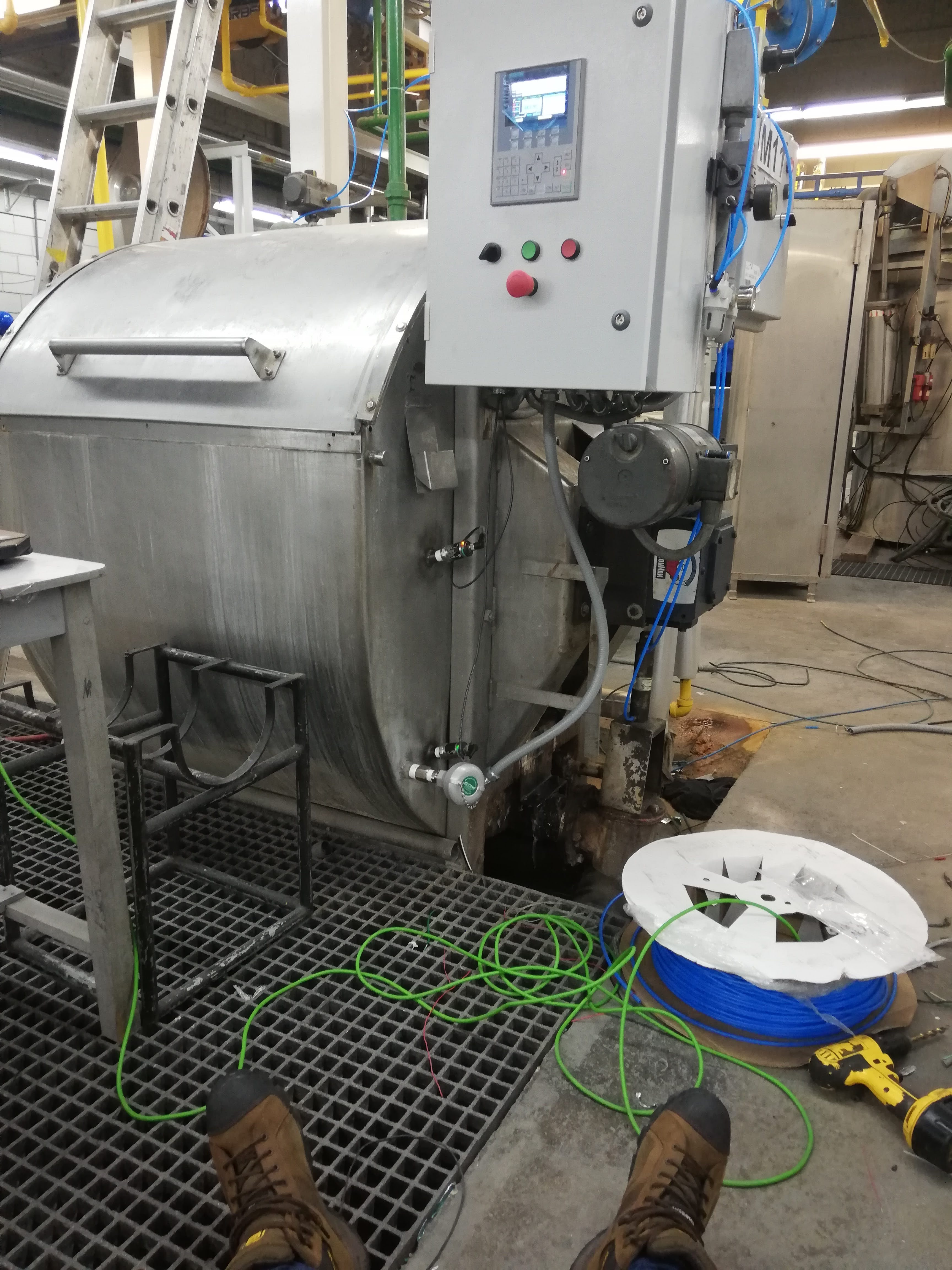 Phase 1 (Advisory): Onboarded as an external technical consultant to support the plant’s internal automation team.
Phase 2 (Lead Engineer): Following the resignation of the lead in-house automation engineer, assumed full responsibility for system architecture, standardized software development, and machine deployment.
Fleet Rollout (12 Total Machines):
Machine 1: Commissioned by the original internal team.
Machines 2–12 (11 Units): Designed, standardized, adapted, and commissioned independently.
Handling Machine-to-Machine Variance
Because physical units differed across the plant floor (e.g., smaller capacity drums requiring fewer chemical valves vs. larger units with extended 8-valve dosing manifolds and distinct level switches), maintaining separate PLC code branches was unfeasible.
The software engine abstracted physical hardware via Configurable Hardware Mapping Tables stored in PLC Data Blocks:
Unified Baseline Logic: A single, standardized PLC program was deployed across all 11 units.
Local Machine Profiling: Physical hardware parameters (e.g.,
Max_Chemical_Valves_Available,Level_Sensor_Type,VFD_Max_Frequency) were defined per machine in a local setup Data Block.HMI Dynamic Rendering: The HMI dynamically hid or exposed chemical dosing options and valve choices based on the local machine profile, preventing operators from selecting non-existent physical outputs.
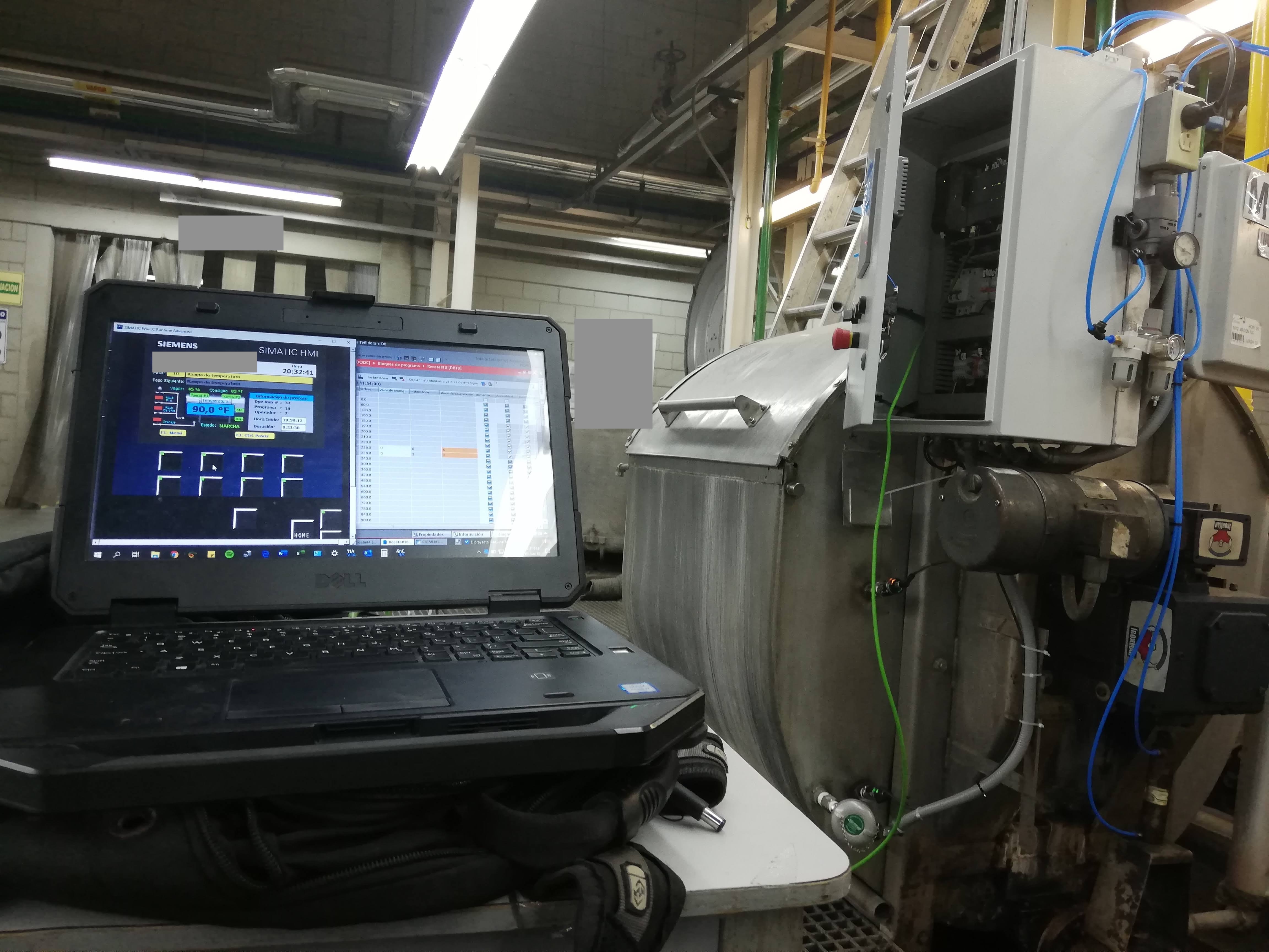 5. Project Outcome & Pattern Legacy
Operational Impact: The recipe system was fully deployed and actively driving daily production across all 11 standardized units, granting plant operators full recipe control via HMI with zero PLC software intervention required.
MES Transition & Scope Conclusion: The edge recipe engine was fully commissioned and validated in active production. The system provided the operational baseline for a planned plant-wide MES integration, which was ultimately suspended due to a facility shutdown.
Architectural Legacy: The decoupled array-based step execution pattern developed for this project served as the foundation for subsequent systems across my portfolio, including:
Cartesian Motion Control: Adapted to drive coordinate sequence step parsers in multi-head CNC embroidery systems.
Automated Testing & Simulation: Evolved into step-based automated test runners and template/instance software execution patterns in higher-level OT/IT platforms.

Oscar Calix
Sr, Control System Engineer
Cloud computing for OT, industrial data pipelines, SCADA supervision, full-stack tools for automation workflows..