RETURN_TO_LOGS
//
#Digital Twin#Siemens S7#Ignition#C#
EdgeTwin in Practice: A Working Digital Twin in 5 Steps
The Project
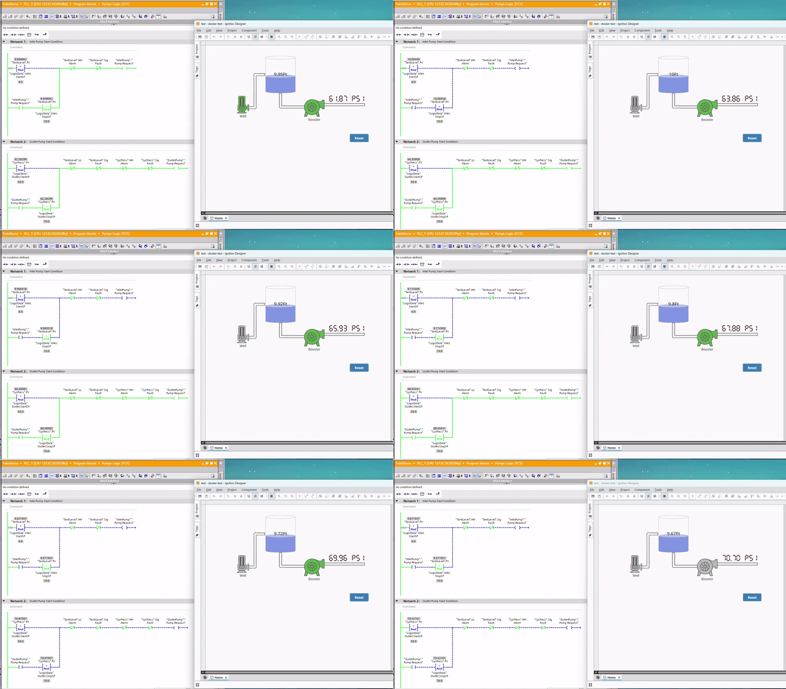
A real S7-1212C running its actual ladder logic. An Ignition HMI animating live. And no physical process — the tank, the pumps, and the pressure are all EdgeTwin. Here's the whole build, step by step.
The process is a simple well-to-distribution segment: an inlet pump fills a storage tank, and a booster pump pressurizes the discharge line. The PLC runs the control logic — start the inlet pump when tank level drops below 6.0 ft, stop it at 10.0 ft; run the booster between 55 and 70 PSI — with standard interlocks (HH/LL alarms, signal faults). The PLC thinks it's reading real transmitters.
For the twin, we deliberately kept the physics simple — no fluid dynamics, just rates:
Tank level: while the inlet pump runs, level increases at a configured rate (ft per second); while the booster draws from the tank, it decreases at its own rate. That's the whole model.
System pressure: same pattern — pressure ramps up at an increase rate while the booster runs, and decays at a decrease rate when it stops.
Both rates are just template ports, so they're tunable per instance without touching code. Simple as it is, this is enough to give the PLC a continuously moving process — real hysteresis between setpoints, real timing — instead of static test values.
Step 1 — Connect to the PLC and browse its tags

Point EdgeTwin's Siemens explorer at the 1212C. It discovers the tags the logic already uses — TankLevel, SysPress, the pump requests. No address bookkeeping.
Step 2 — Create the project
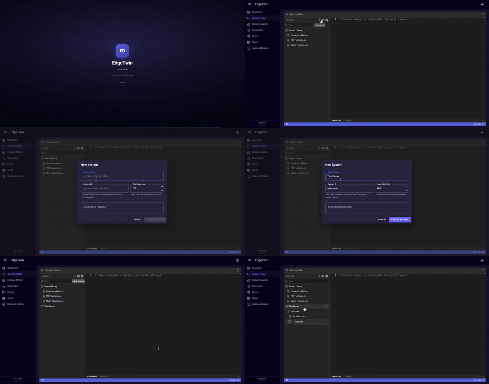 One project = one plant model. Takes seconds.
Step 3 — Create the templates
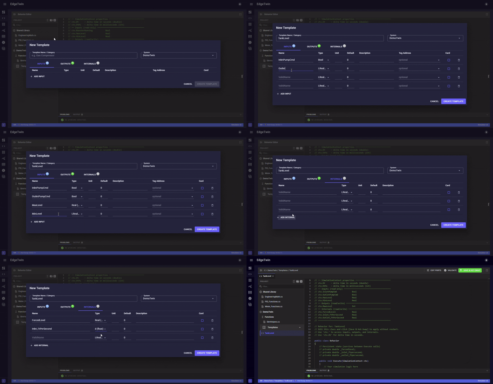 A template is just ports (inputs, outputs, internals) plus a C# behavior. Three templates cover this whole demo.
Pump — a run command doesn't mean instant running: 1-second start delay, confirmation, fault pass-through.
public class Behavior
{
  private double secElapsed = 0;

  public void Execute(SimulationContext ctx)
  {
    if (ctx.RunCmd)
      secElapsed += ctx.DtMs;
    else
      secElapsed = 0;

    ctx.RunStatus = !ctx.CtrExternalFault
    && secElapsed > 1000
    && (ctx.AutoConfirm || ctx.ManualConfirmation);

    ctx.Auto = ctx.CtrAuto;
    ctx.Hand = ctx.CtrHand;
    ctx.ExternalFault = ctx.CtrExternalFault;
  }
}
Tank — level integrates up while the inlet runs, down while the outlet runs, then converts to raw Siemens counts (0–27648) and writes straight into the PLC's input register:
public class Behavior
{
    private double currentScaledLevel = 0;
    private bool initialized = false;

    public void Execute(SimulationContext ctx)
    {
        if (!initialized)
        {
            currentScaledLevel = ctx.MinLevel;
            initialized = true;
        }
        if (ctx.InletPumpCmd)
            currentScaledLevel += ctx.Inlet_FtPerSecond * ctx.Dt;

        if (ctx.OutletPumpCmd)
            currentScaledLevel -= ctx.Outlet_FtPerSecond * ctx.Dt;

        currentScaledLevel = EngineeringMath.Clamp(currentScaledLevel,

        ctx.MinLevel, ctx.MaxLevel);
        ctx.RawLevel = Convert.ToInt16(
        EngineeringMath.ToRaw(currentScaledLevel, ctx.MinLevel, ctx.MaxLevel, 0, 27648));
    }
}
Pressure — same pattern: ramps while the booster runs, decays when it stops.
public class Behavior

{
  private double currentScaledPressure = 0;

  private bool initialized = false;

  public void Execute(SimulationContext ctx)

  {
    if (!initialized) {
      currentScaledPressure = ctx.MinPressure;
      initialized = true;
    }

    if (ctx.BoosterRunning)

      currentScaledPressure += ctx.IncreaseRate * ctx.Dt;

    else

      currentScaledPressure -= ctx.DecreaseRate * ctx.Dt;

    currentScaledPressure = EngineeringMath.Clamp(
        currentScaledPressure, ctx.MinPressure, ctx.MaxPressure);

    ctx.RawPressure = Convert.ToInt16(

        EngineeringMath.ToRaw(currentScaledPressure, ctx.MinPressure,
                              ctx.MaxPressure, 0, 27648));
  }
}
Note that EngineeringMath isn't defined here — it's a global helper library, so scaling math is written once and every template just calls it.
Step 4 — Create instances and bind them
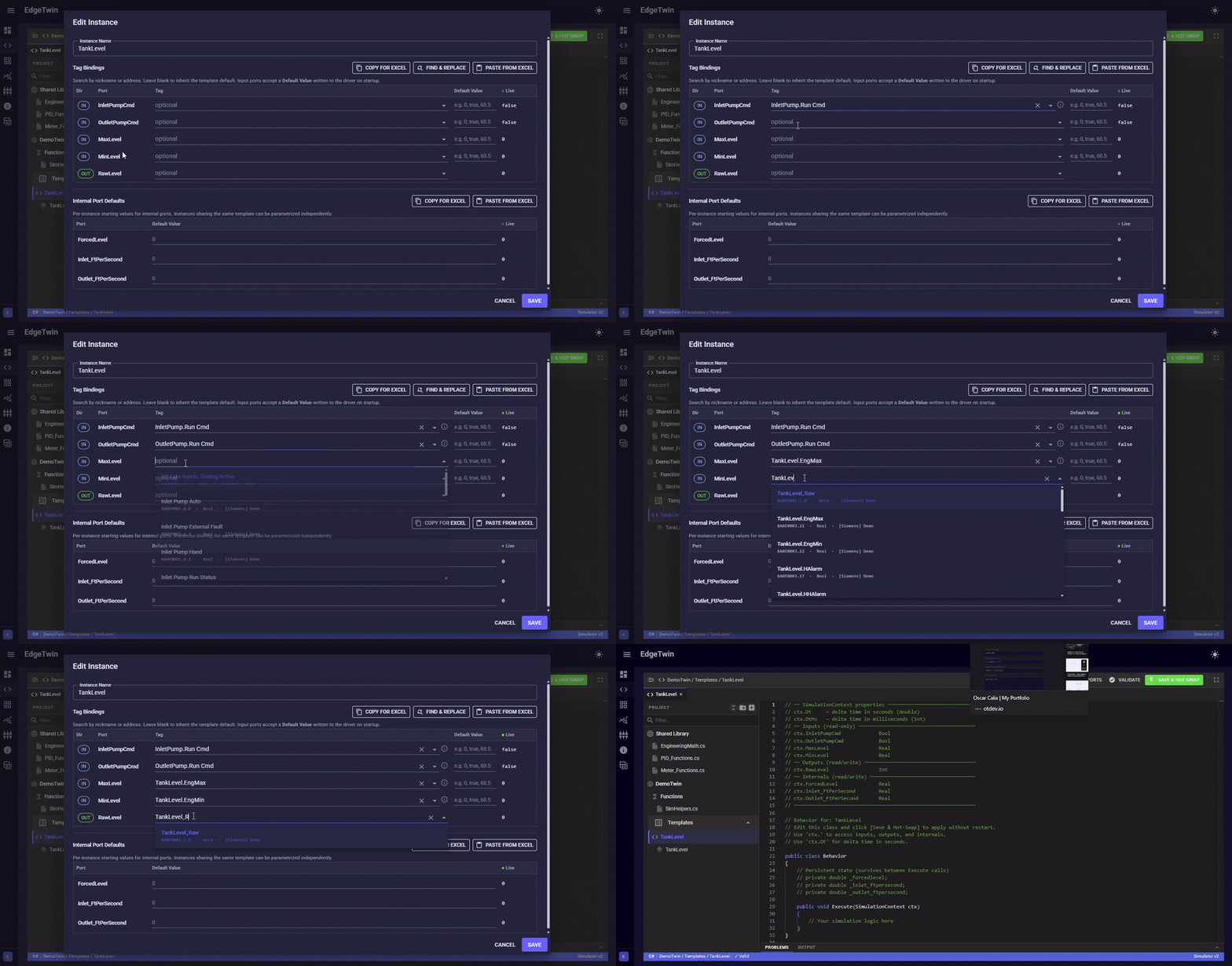
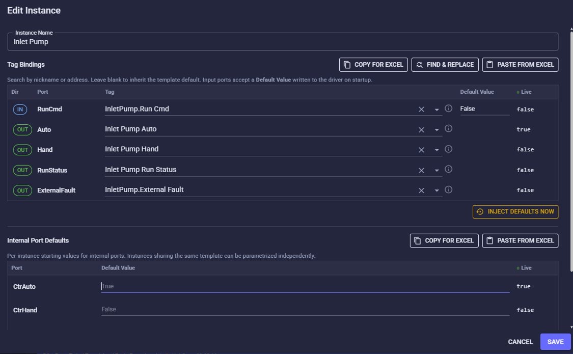
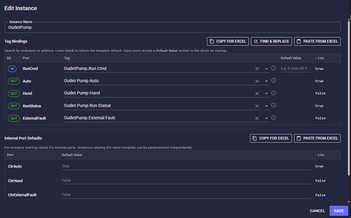
The Pump template becomes two instances (inlet and outlet), each bound to its own PLC tags from Step 1. Tank and Pressure get one instance each. Binding a port to a tag is a dropdown, not code.
Tank Level
 Inlet Pump
 Outlet Pump (Booster)
 System Pressure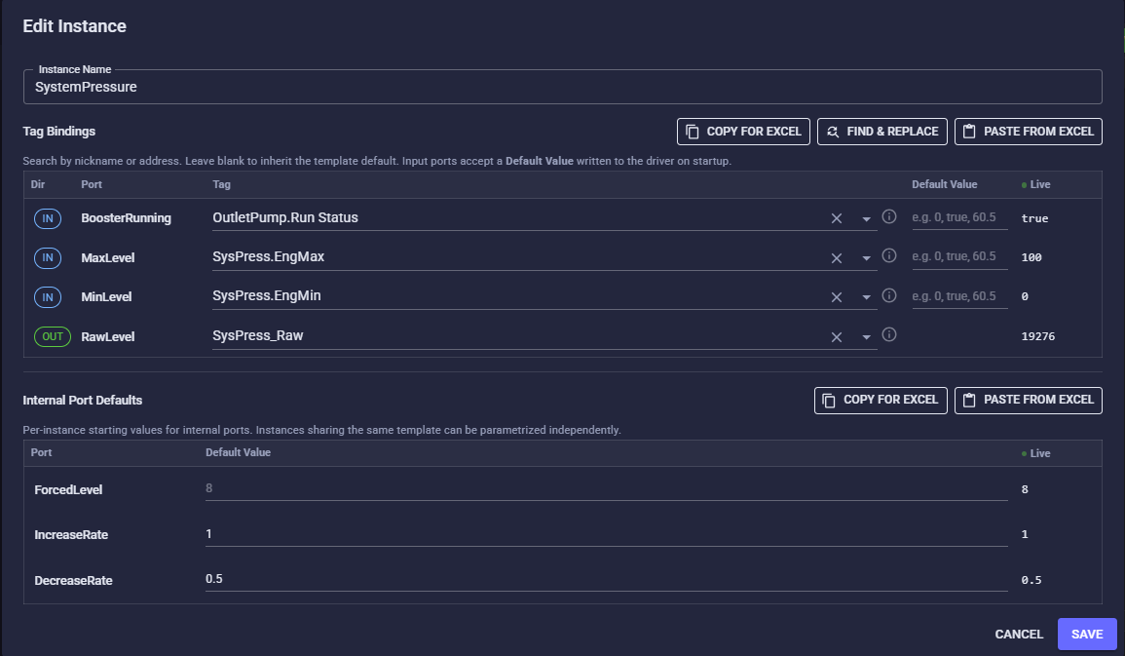
Step 5 — Run It
That's it. EdgeTwin writes computed raw values into 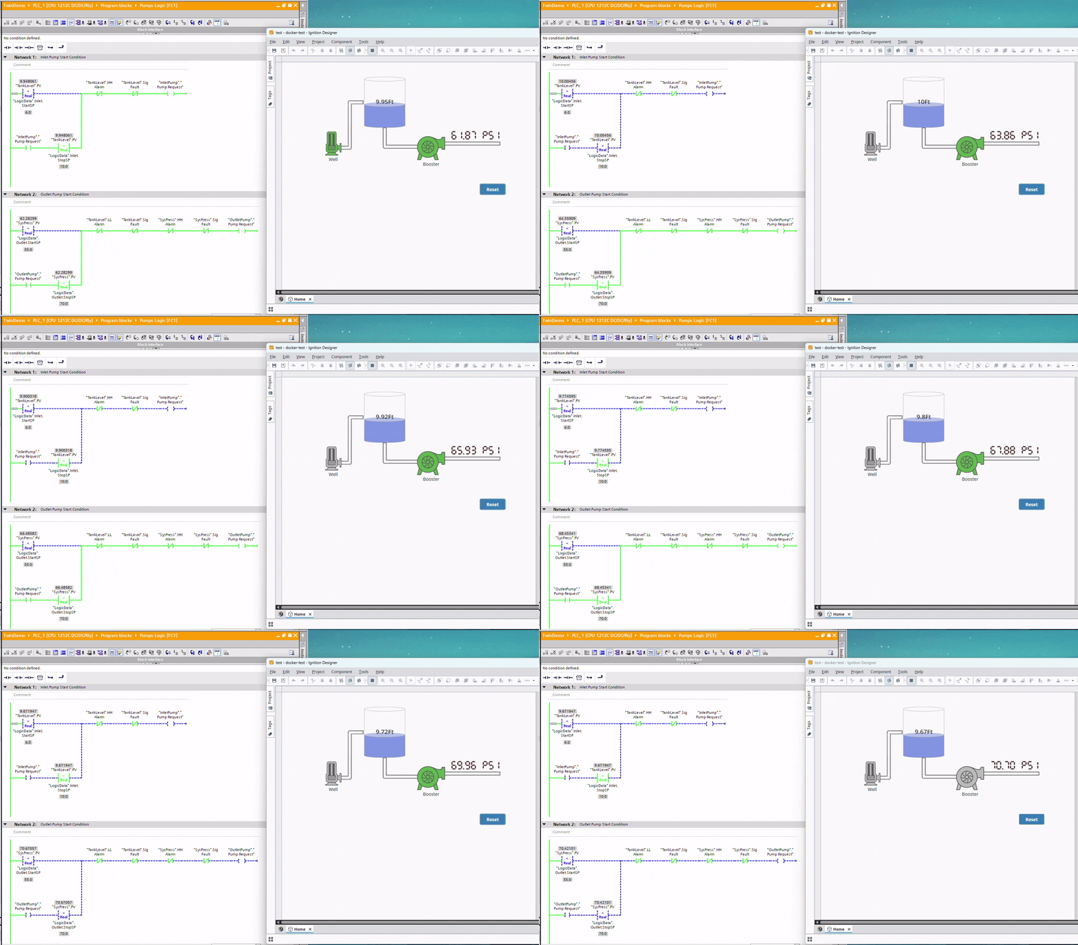 the PLC's input registers every scan; the PLC runs its interlocks and commands the pumps back. Level cycles between the setpoints, pressure cycles 55–70 PSI, and Ignition animates it all live.
Total build time: about 10 minutes. Three short behaviors, four instances, zero field hardware — and the PLC logic, analog scaling, and HMI all got validated against a moving process instead of typed test values.
Oscar Calix
Sr, Control System Engineer
Cloud computing for OT, industrial data pipelines, SCADA supervision, full-stack tools for automation workflows..
END_OF_TRANSMISSION